Two pages taken from Brian’s notebook, detailing parts of the construction process of the Red Special. Written in his own hand just after the guitar was finished (thus dating the original documents to late 1964), it adds yet more detail to the build and are just two of many private papers the team had access to during the research for and compilation of the Brian May’s Red Special book.
These notes also appear on pages 32/33 of the book, but we thought it’d be useful to transcribe the copy into a format that can be more easily read. Needless to say, the book contains many more examples of Brian’s original work, including exquisite pencil drawings of designs for pickups, graphs denoting differing scale lengths, and much more.
========================================================================
<page one>
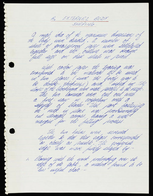
A – External Body Shaping
A rough idea of the maximum dimensions of the body were decided. A number of sheets of greaseproof paper were sellotaped together and the outline was drawn full size on these sheets in pencil.
With carbon paper the tracing was transferred to the material to be used in two places (and the body was to be double-thickness) and inked in. The strips of the blockboard were made parallel to the neck.
The two laminates were cut out with a fret-saw in a conjunction with a supply of blades. That part fastening the neck in place was provisionally cut straight across, leaving a wide margin for the fretting process.
The two halves were screwed together so that their edges corresponded as closely as possible. The composite edge was more finely shaped by:
1 – Planing with the work protruding over the edge of the table, a method found to be less useful than:
<page two>
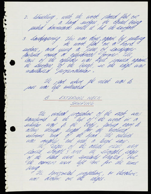
2 – Chiselling, with the work placed flat on a hard surface, the chisel being pushed downwards until it hit the surface.
3 – Sandpapering. This was done, again by putting the work flat on a hard surface and using a piece of sandpaper fastened round a cylindrical former. The case of the cylinder was kept pressed against the surface of the bench, so the edge was maintained perpendicular.
The part where the neck was to join was left untouched.
B – External Neck Shaping
The vertical projection of the neck was transferred to the top of the wood in a similar way to the body, taking care to allow enough length for the inclined extreme end of the head. The outline was roughly cut with a tenon saw.
The edges of the actual neck were planed straight, and the straight edges of the head were similarly treated, but the corners were left on for the time being.
The horizontal projection, or elevation, was drawn on the edges.
========================================================================
By all means share these photos, but please credit The Red Special.com should you do so.
Don’t miss Simon’s six-part blog that goes behind the scenes of the book in much more detail
For part one click here
For part two click here
For part three click here
For part four click here
For part five click here
For part six click here